









Dispensing from Cartridges: Where Every Thermal Job Actually Starts
Every job starts with a 300 cc cartridge or smaller. Nobody buys a 20-liter pail of gap filler on day one. The material comes in as a 300 cc cartridge, sometimes a 30, 75 or 180 cc, sometimes a side-by-side 2×300 cc for two-part products, and the first question is whether it can be put down as a repeatable bead on a real part. Most of what we do at Dispense Robotics starts right there, and it's the part of the process that most equipment presentations leave out.
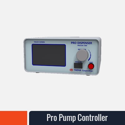
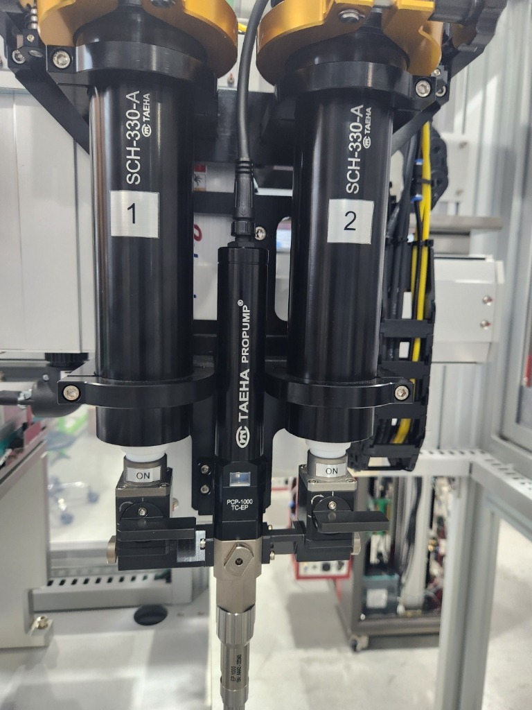
Caption: Two 330 mL cartridges mounted directly in push units on a dual-channel PCP-1000 dispenser. No hose, no reservoir — the cartridge feeds the pump directly.
What a Cartridge of TIM Really Is
A thermal interface material is a carrier, usually silicone, packed with ceramic or metal filler. That filler is what gives you the thermal conductivity, and it also makes the material heavy, abrasive and reluctant to flow. A cartridge of Laird Tputty 607 has a density of 3.45 g/cc, so a 6 oz cartridge that nominally holds 180 cc weighs about 556 g. A 1 cc shot of a material at 3.1 specific gravity weighs 3.1 g. When you specify shot size by weight, as you should for filled materials, those numbers are what the pump has to deliver, every shot, as the filler wears the pump.
Pushing that out of a cartridge with an air gun is fine for a sample. It's not a process. Air pressure on a cartridge of high-viscosity, high-filler material gives you a shot that changes with temperature, with how much is left in the cartridge, and with how long the gun sat between shots.
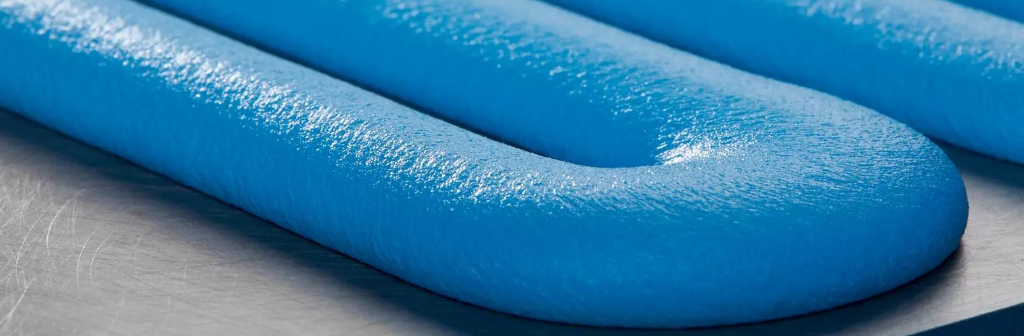 Caption: A dispensed thermal interface material bead, close up. This is what a filled, high-viscosity TIM looks like when the shot weight and bead profile are actually under control.
Why We Start With the Cartridge and a Positive-Displacement Pump
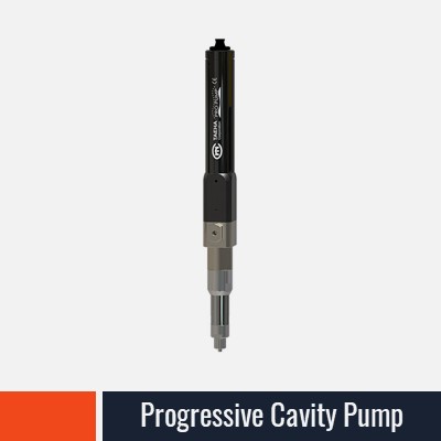
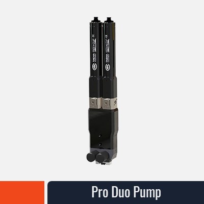
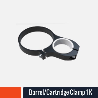
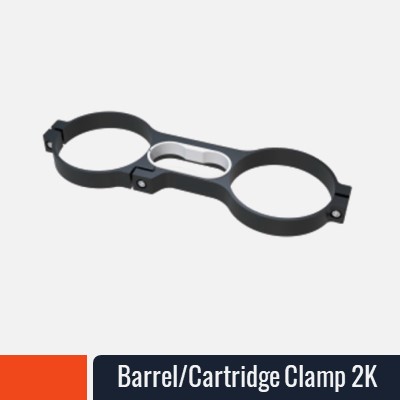
Our approach is to mount the cartridge directly on a progressive-cavity pump through a push unit. The push unit feeds the material out of the cartridge under controlled pressure, and the pump meters it. There's no hose, no reservoir and no extra plumbing between the material and the point of dispense, which matters when the material is abrasive and the volume you have to work with is 300 cc. For two-part materials, two push units feed the A and B sides into a 2K pump that holds the ratio.
One note on ratio, because it's where filled two-part materials go wrong. The pressure transducers on a 2K system are not a calibration. The specific gravity of a filled material varies from batch to batch, and the pumps wear, so we have customers take a weight sample from each side once a week and adjust each pump on its own. That single habit catches material variation and pump wear before either one shows up as a cure problem.
That configuration does three jobs for a customer. In the lab, it lets an engineer qualify a material on the actual part with the same shot weight and bead profile the production line will use, from a single cartridge, before anyone commits to a pail. In prototyping and low-volume build, it runs as the production system, because a progressive-cavity pump doesn't care whether it's fed from a cartridge or a pail. And on the floor, it's the rework station: when a module fails and the gap filler has to be reapplied on one part, a cartridge-fed pump does that without disturbing the main line.
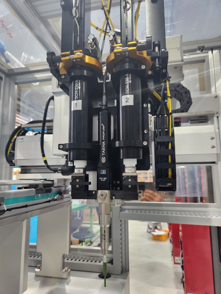 Caption: The same setup mounted on a gantry — the lab qualification rig and the production dispenser are the same hardware.
From Cartridge to Pail Without Changing the Process
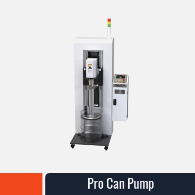
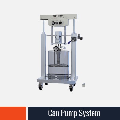
When volume justifies it, the same pump moves onto a pail feed system, either a 5-gallon pail or a 20-liter can pump with a follow plate that leaves under 1% of the material behind. The dispense head, the shot weight and the bead don't change. What changes is how the material gets to the pump. That continuity is the point: the cartridge trial you ran six months ago is the production process, not a rough approximation of it.
The Materials This Was Built Around
The systems in the linked presentation were developed around a specific group of thermal materials: Laird Tputty 607, NanoTIM TGF-NT300UL, Henkel Bergquist Gap Filler TGF-12000, Nolato Compatherm Filler 9290 and Parker Lord CoolTherm SC-1600. They span single-part and two-part, conductivities from 3 to 12 W/m·K, and densities from 1.85 to 3.45 g/cc. Every one of them ships in a cartridge before it ships in a pail. If you're working with one of these, or with something similar from Dow, Henkel or Parker, we've probably already run it.
See the Full Range
Our TIM Dispensing Solutions presentation covers the application side, from EV battery packs and ICCU housings to semiconductor packages, 5G modules and maritime repeaters, along with the pump, push-unit and pail-feed lineup for each. You can view the presentation here (opens in a new tab).
If you have a cartridge of something on your bench and aren't sure how it will dispense, send us the TDS at gavin@dispenserobotics.com. We'd rather look at your material before talking about equipment.
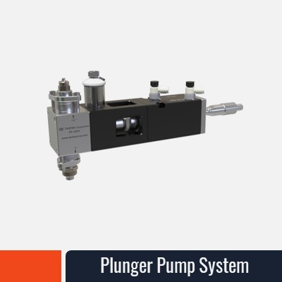
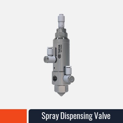
Dispense Robotics is based in Ormond Beach, Florida. Our pumps and feed systems are manufactured by TAEHA Corporation, Korea, and supplied, integrated and supported in North America by Dispense Robotics.
Gavin Petersen has spent 30+ years in industrial fluid dispensing, including senior roles at Graco. He works with engineers to get a filled thermal material from a cartridge on the bench to a repeatable bead on the line, without the process changing in between.