


Thermal Interface Material Dispensing for EV Battery Pack Assembly
Electric vehicle battery packs generate significant heat during charge and discharge cycles. Without effective thermal management, localized hotspots can exceed safe operating temperatures, triggering degradation pathways that reduce cycle life and create thermal runaway risk. Thermal interface material dispensing—the precise application of TIM compounds between cells, modules, and cooling substrates—is a critical manufacturing control point in modern EV battery assembly. Precision in thermal interface material dispensing directly determines whether your battery pack achieves rated performance and safety targets.
The challenge facing automotive battery manufacturers isn't simply using thermal interface materials. It's applying them with the right volume, uniformity, and coverage to meet thermal resistance specifications while maintaining production speed and cost efficiency. Voids, thin spots, and application inconsistencies translate into thermal resistance variations that degrade heat transfer and create reliability risks across your battery fleet.
This guide walks process and manufacturing engineers through thermal interface material selection, dispensing machine capabilities, process parameters, and real-world application strategies for EV battery pack assembly.
What Is Thermal Interface Material (TIM)?
Thermal interface materials are engineered compounds designed to fill micro-scale voids between mating surfaces and reduce thermal contact resistance. In EV battery packs, TIMs bridge gaps between cells and cold plates, cell tabs and bus bars, pouch cell facings and module frames, and other high-thermal-demand interfaces.
TIM types differ in form factor, application method, and performance characteristics:
Thermal Grease and Paste
Liquid-consistency compounds (typically 50,000–500,000 cP viscosity) that conform to surface irregularities and fill voids under compression. Examples include Dowsil TC-5026 and Henkel Bergquist GP3000. Grease and paste are dispensable via automated systems and provide excellent coverage uniformity. They remain somewhat compliant under thermal cycling, reducing interfacial stress. Trade-off: they migrate and pump out under repeated compression cycles if not formulated with thixotropic stabilizers.
Phase-Change Materials (PCM)
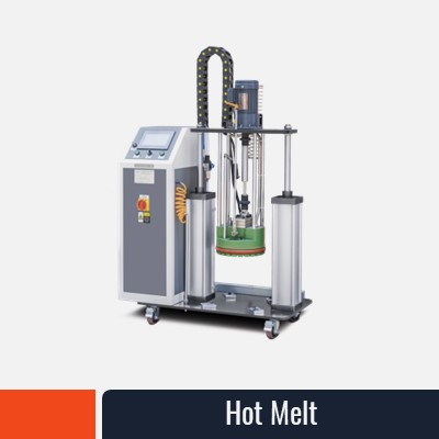
Solid or semi-solid compounds at room temperature that soften or flow when heated during assembly pressure and cure. They offer higher thermal conductivity than grease (often 3–6 W/m·K vs. 1–3 W/m·K) and superior dimensional stability. PCMs require precise heating and pressure control during assembly but eliminate pump-out risk over battery life. They cannot be applied via standard dispensing equipment and typically arrive as pre-cut pads or require specialized hot-melt dispensers.
Gap-Filler Compounds
Viscous pastes (80,000–300,000 cP) formulated to remain in place within wider gaps (0.5–2 mm) without bleeding or migration. They're dispensable, offer mid-range thermal conductivity, and work well for module-to-frame interfaces. Bergquist Gap Filler materials are standard in automotive battery assembly.
Adhesive-Based TIMs
Compounds that simultaneously bond and conduct heat. Used when mechanical fastening is not desired and structural adhesion is beneficial. Dispensable via automated pumping systems; cure time and fixture requirements vary.
Pressure-Sensitive Adhesive (PSA) Pads
Pre-manufactured, self-adhesive sheets or cut-to-size pads. Zero dispensing required but inflexible in application pattern and often higher cost per interface. Suitable for high-volume, repetitive geometries.
Each type serves distinct thermal and mechanical requirements. Grease and gap-filler compounds dominate in EV battery dispensing workflows because they combine dispensing ease with cost efficiency and proven thermal performance.
Why TIM Application Precision Matters in EV Battery Packs
Thermal interface material dispensing precision directly impacts battery pack thermal resistance, temperature distribution, and cell-level degradation rates.
Thermal Resistance and Temperature Deltas
Thermal contact resistance at a cell-to-cold-plate interface—without TIM—can reach 0.5–1.0 K/W or higher, depending on surface finish and pressure. Proper TIM application (grease at 50–150 µm thickness, full coverage) reduces that resistance to 0.05–0.15 K/W. The difference translates directly to temperature delta: a 100 A discharge on a cell with 0.5 K/W contact resistance and 10 W dissipation creates a 5°C temperature rise at the interface alone. With optimized TIM, that same cell sees <1°C rise at the contact point, keeping bulk pack temperature lower and extending cycle life.
Void and Thin-Spot Consequences
Voids—even small air pockets occupying 5–10% of the interface area—create localized "hot spots" because air conducts heat ~1,000× slower than thermal paste. A 10% void fraction in a 100 cm² interface area effectively removes 10 cm² of thermal conduction, concentrating heat into surrounding regions and raising local cell surface temperature by 3–8°C depending on power and geometry. Thin spots (coverage <50 µm on areas intended for 100 µm) show similar effects.
Field data from EV battery packs with insufficient TIM coverage show:
- 15–25% increase in cell temperature variance across a 96-cell module
- Accelerated degradation on 5–15% of cells due to higher localized temperatures
- Cycle life reduction of 10–20% under fast-charge conditions where thermal control is most critical
Uneven Volume and Coverage Uniformity
Dispenser drift, worn pump components, or inconsistent surface preparation lead to volume variations of ±20–30% across the production run. While individual cells may still fall within acceptable thermal resistance windows, cumulative effects across a 96+ cell pack create temperature distribution imbalances. Cells with lower TIM coverage operate 2–5°C hotter, accelerating lithium-plating and SEI growth degradation pathways.
Regulatory and Safety Standards
IEC 62660 and UL 2580 battery safety standards require manufacturers to demonstrate thermal management capability, including testing at elevated ambient temperatures (55–60°C). Poor TIM application margins increase the risk of cell-level thermal excursions during abuse testing and reduces the thermal buffer available for real-world transient events.
Precision thermal interface material dispensing is not a peripheral process control—it is a first-order determinant of EV battery thermal performance and longevity.
How Thermal Interface Material Dispensing Works
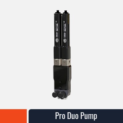
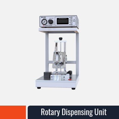
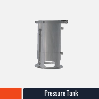
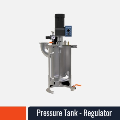
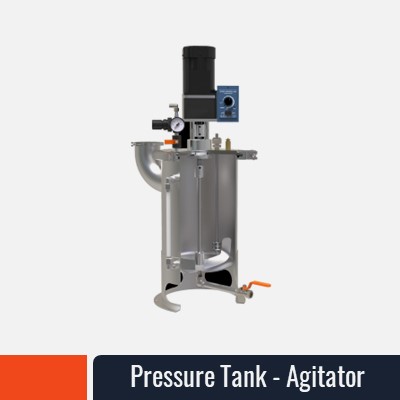
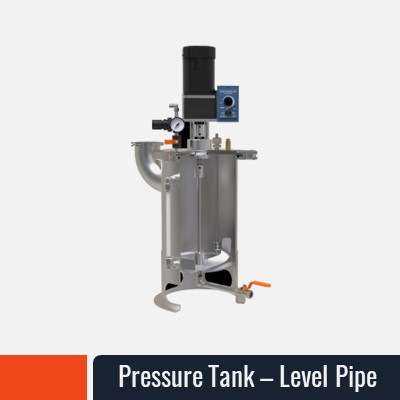
Automated thermal interface material dispensing systems apply TIM compounds in controlled bead patterns, volumes, and cure states using positive displacement pumps, heated reservoirs, and motion control systems integrated into the battery assembly line.
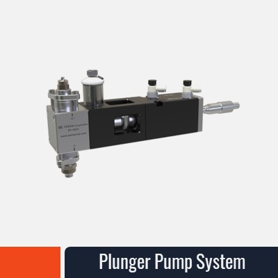
Positive Displacement Pumping
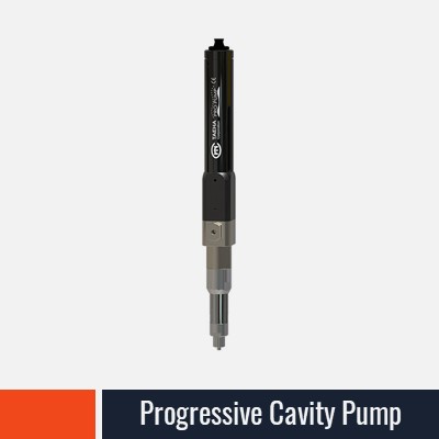
Progressive cavity (rotary screw) pumps are the standard for EV TIM dispensing. These pump types maintain volumetric displacement proportional to motor RPM, delivering consistent flow rates across the viscosity range required for grease and gap-filler compounds (50,000–500,000 cP). Unlike gear pumps, progressive cavity designs avoid cavitation and shear heating of viscous, thermally sensitive TIM compounds. Pump displacement typically ranges from 0.1–10 mL/rev, allowing fine-tuned flow control.
Piston and diaphragm pumps handle lower-viscosity, 1-part TIMs and specialized low-volume applications. Progressive cavity pumps remain dominant in high-viscosity, high-throughput battery assembly.
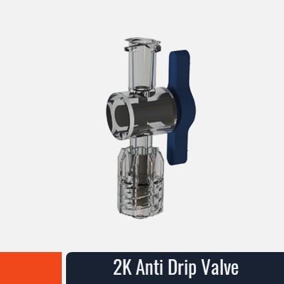
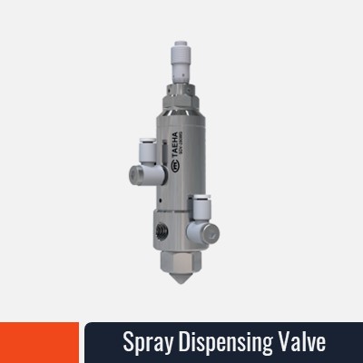
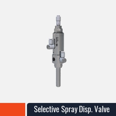
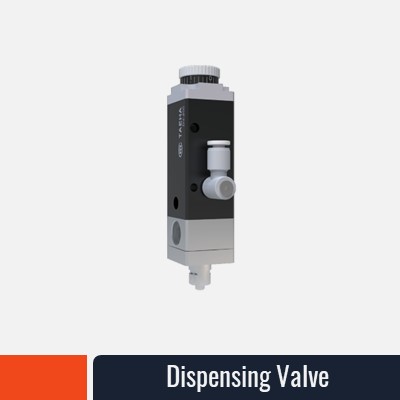
Dispensing Head and Valve Technology
Dispense heads seat above the interface point, delivering TIM through a heated cartridge or direct pump line. Poppet or ball-check valves prevent back-drool (TIM flow during non-dispensing intervals), which creates drips, thread-ups on tool changers, and surface contamination. Heated dispense tips (set to 30–60°C depending on TIM formulation) maintain ideal flow properties and prevent premature cure or gelation.
Bead Pattern Strategies
Different interface geometries and thermal demands call for distinct bead patterns:
- Serpentine (snake pattern): Single continuous bead following a parallel-line path across the interface. Delivers good coverage uniformity for rectangular cell-to-cold-plate interfaces. Typical bead widths: 2–4 mm, spacing 10–15 mm.
- Dot matrix: Regular grid of small dots or circles, spaced 15–30 mm apart. Fast to dispense, good for modular assembly. Risk of incomplete coverage if dots are too sparse.
- Perimeter + crosshatch: Bead applied around the interface perimeter and in a lattice across the middle. Maximizes coverage uniformity for large irregular geometries, requires longer dispense time.
- Full-face flood coat: TIM applied across entire interface area in a thin, even layer. Highest coverage assurance but highest material consumption and longest cure/compression time.
Most EV battery cell-to-module interfaces use serpentine or perimeter + crosshatch patterns to balance coverage, material cost, and dispense cycle time.
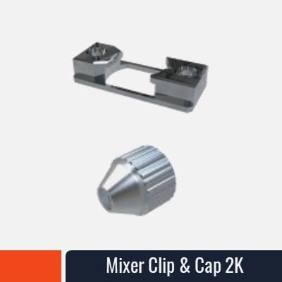
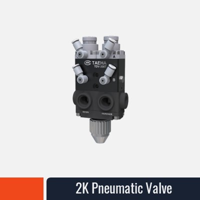
2-Part Material Mixing
Many advanced TIM compounds (especially phase-change materials and high-performance gap fillers) are supplied as 2-part systems: resin + hardener. Automated mixing systems—static mixers, dynamic ribbon impellers, or dual-cartridge mixing heads—blend the two components in precise stoichiometric ratios (typically 1:1, 2:1, or 10:1) immediately before dispensing. Improper mix ratios create cure failures, viscosity drift, or incomplete cross-linking, all of which degrade thermal performance. Progressive cavity pumps paired with metering cartridges ensure repeatable ratio control across high-volume runs.
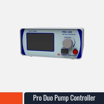
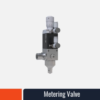
Volumetric Control and Feedback
Dispenser systems log motor current, encoder pulses, and time-to-dispense for each cycle. Deviations in expected flow rate (typically ±5–10%) trigger alerts for worn pump components, nozzle clogs, or viscosity drift. Online weight scales or camera-based vision systems verify dispensed volume on sample parts, closing the feedback loop to ensure each battery pack assembly receives the target TIM charge.
TIM Dispensing Challenges in EV Battery Manufacturing
Thermal interface material dispensing at scale introduces multiple technical and operational hurdles specific to automotive battery assembly environments.
High Viscosity and Shear Sensitivity
Typical TIM compounds for EV batteries range 100,000–400,000 cP—far thicker than adhesives or conformal coatings. Pushing high-viscosity fluids through small nozzles requires significant pump pressure, raising the risk of heat generation, viscosity reduction, and potential cure acceleration in 2-part materials. Shear-sensitive TIM formulations (especially some phase-change and elastomeric gap fillers) lose thermal performance if over-worked by pump impellers or high-velocity nozzles. Selecting a dispenser that minimizes shear stress—large pump chambers, low nozzle velocities, moderate pressure profiles—is critical.
Pot Life and Shelf Life Constraints
2-part TIM systems have finite pot life after mixing, typically 4–24 hours depending on formulation and ambient temperature. In high-volume battery assembly (1,000+ packs per shift), dispenser systems must be purged and re-charged frequently, creating material waste and downtime. Some systems employ heated, sealed cartridge storage and automated metering to extend working windows. Others use 1-part systems to avoid mixing overhead, trading thermal performance for process simplicity.
Mixing Ratio Precision
Off-ratio mixing (e.g., 1:1 intended but delivered at 1.05:1 or 0.95:1) creates viscosity drift, incomplete cross-linking, or exothermic runaway in highly exothermic systems. Manual cartridge loading or simple pump metering introduces ±5–10% ratio errors. Dual-cavity positive displacement pump designs or weight-feedback mixing systems hold ratio error to <2%, enabling consistent cure kinetics and thermal performance across the production batch.
Temperature Sensitivity
TIM compounds are temperature-sensitive: viscosity changes 5–10% per 5°C in typical formulations. Assembly lines that operate 24/7 across seasonal temperature swings (factory ambient 15–28°C) see viscosity drift that requires periodic pump speed recalibration or dispense-pressure adjustment. Some advanced systems include inline temperature sensing to auto-adjust flow rate and maintain constant viscosity output.
Speed at Volume
EV battery pack assembly targets 200–400 packs per shift, with 20–50 TIM application points per pack (cells, modules, cold-plate bonds, etc.). That translates to 4,000–20,000 TIM dispense events per shift. Dispenser systems must achieve <2-second cycle time per dispense point—including approach, dispensing, retract, and surface contact—to avoid bottlenecking the line. Slow pumps, large bead volumes, or long cure times (requiring fixture hold time) become line-rate stoppers.
Line Integration and Contamination Control
EV battery assembly increasingly occurs in ISO Class 6–7 cleanroom or semi-cleanroom environments to control particulate contamination and moisture. Dispenser carts and pump units must fit within material-handling constraints, connect via quick-disconnect lines that prevent drips and outgassing, and integrate without creating dust or off-gassing sources. Dispense heads that cool post-application prevent thermal curing inside the nozzle, reducing material buildup and maintenance frequency.
Choosing a TIM Dispensing Machine for EV Applications
Selecting the right thermal interface material dispensing equipment requires evaluation across technical and production criteria. The equipment selection side — pump type, valve material, fluid path — is covered in depth in Thermal Interface Material Dispensing: Equipment Selection for Abrasive TIMs.
1. Viscosity Range and Pump Type
Specify the minimum and maximum TIM viscosity you will dispense. Progressive cavity pumps handle 50,000–500,000 cP efficiently; piston or diaphragm pumps excel below 50,000 cP but struggle with gap fillers. If you plan to dispense Dowsil TC-5026 grease (150,000 cP) and Bergquist Gap Filler (250,000 cP) from the same machine, progressive cavity is non-negotiable. Verify that the dispenser supplier can provide pump displacement ratios (mL/rev) suitable for your target dispense volumes (typically 0.1–2 mL per interface point). Undersized pumps require excessive RPM, generating heat and shear; oversized pumps lose resolution control.
2. Throughput and Cycle Time
Define your production target: packs per shift and TIM dispense points per pack. If you run 400 packs per shift with 30 dispense points each, you need 12,000 dispense events per 8-hour shift—roughly 1.5 dispenses per second across all workstations. A single dispenser can handle this if located at a centralized gantry or multi-axis robot station. If dispensing is decentralized (per-module stations), each dispenser can operate at lower throughput. Confirm that the dispenser's approach time, nozzle retract speed, and purge cycle support your line rate without creating bottlenecks.
3. Mixing Capability for 1K vs. 2K Materials
If your TIM strategy includes 2-part compounds (for higher thermal conductivity or cure control), the dispenser must feature automated metering and mixing. Dual-pump or dual-cavity progressive cavity systems deliver repeatable ratios <2% error. If you are committed to 1-part materials only, mixing capability becomes unnecessary, reducing equipment cost and complexity. Evaluate your thermal performance targets and cost trade-offs: 2-part systems often offer 20–30% higher thermal conductivity but require dispenser investment and operator training.
4. Dispensing Accuracy and Repeatability
Most production applications require ±10–15% volumetric accuracy (e.g., 1.0 mL ±0.1–0.15 mL per dispense). This is achievable with modern progressive cavity pumps and encoder feedback. Verify the dispenser's repeatability specification—standard deviation across 50+ consecutive dispenses—and whether the system includes real-time feedback (weight scale, vision, or displacement counting) to detect drift and alert operators before out-of-spec parts ship. If you're seeing shot weight drift or coverage inconsistency mid-production, filler settling is usually the cause.
5. Cleanroom and Line Integration
If your assembly line operates in ISO Class 6–7 (for cell-level cleanliness), confirm that the dispenser cartridge, pump head, and connecting lines do not off-gas or generate particulate. Stainless steel and PTFE-lined components are standard. Specify heated dispense tips and rapid-cool features to prevent TIM cure inside the nozzle. Confirm that quick-disconnect fittings meet the line's change-over and cleaning protocols.
6. Data Traceability and Compliance
EV battery manufacturers increasingly require traceability: serial number, date, dispense volume, cure time, and lot number for every TIM application on every pack for warranty and recall purposes. Modern dispenser systems integrate with MES (manufacturing execution systems) via Ethernet or hardwired I/O, logging dispense parameters to production databases. If your company operates under IATF 16949 automotive quality standards, confirm that the dispenser supplier can provide SPC data, maintenance logs, and calibration certificates to satisfy audit requirements.
Evaluate equipment based on viscosity match, throughput headroom, mixing capability, accuracy specs, integration readiness, and traceability—not simply on purchase price. A $50k dispenser that delivers 30% scrap due to poor accuracy or integration issues is far costlier than a $75k system purpose-built for your process.
TIM Dispensing in Practice: Application Patterns and Process Parameters
Real-world EV battery dispensing balances thermal performance, cost, and production speed through bead pattern and process parameter optimization.
Bead Width and Coverage
Bead width (2–5 mm) is a function of pump displacement, dispense speed, and nozzle orifice size. A typical configuration dispenses 0.5 mL per 5 cm of bead length, producing a 3 mm wide, 80–120 µm thick line of thermal grease. Multiple passes or flood coating increase coverage at the cost of material and cure time. For a cell-to-cold-plate interface (typically 50–100 cm² per cell), a single serpentine bead pass covers ~60–70% of the interface; designers often accept this, relying on compression under mechanical pressure to redistribute TIM across voids. Alternatively, a perimeter + crosshatch pattern raises coverage to >85% but increases dispense time by 40–60%.
Dispensing Speed and Pressure
Progressive cavity pumps operate at 10–100 RPM for typical TIM compounds, delivering 0.1–2 mL/sec. Higher RPM accelerates throughput but increases shear heating and nozzle pressure. Pressure control (typically 10–30 bar for grease, up to 50 bar for stiff gap fillers) balances flow consistency against pump wear and nozzle clogging. A well-tuned system operates at 15–20 bar average pressure; pressures consistently >50 bar indicate excessive viscosity, partial clogs, or undersized pump displacement.
Working Temperature and Cure Window
TIM compounds are dispensed at 20–60°C depending on formulation. Heated cartridges (thermistors monitoring +/- 2°C) maintain optimal flow viscosity. After dispensing, TIM must remain fluid through mechanical assembly and compression (30–60 seconds typical) before fixture cure begins. 1-part systems often cure at room temperature over 4–24 hours; 2-part systems may cure in 10–60 minutes if formulated for rapid cross-link. Process designers must coordinate dispense temperature, fixture dwell time, and cure initiation to avoid premature gelation (which prevents compression) or excessive cure delay (which extends fixture time and reduces throughput).
Voids and Air Entrapment Prevention
Dispensing viscous TIM compounds into narrow gaps (0.2–0.5 mm) risks air entrapment if the bead is applied too quickly or nozzle velocity is too high. Best practices:
- Dispense at moderate speed (0.5–1 mL/sec) to allow air to escape ahead of the TIM front.
- Use low-nozzle-velocity designs or tapered dispense tips to reduce fluid turbulence.
- Pre-wet the interface with a thin coat on one surface, then apply the second bead on assembly; capillary action pulls the second bead into contact and displaces trapped air.
- Compress the interface immediately after bead application to help TIM flow and fill remaining micro-voids.
Process Parameter Documentation
Document and control:
- TIM lot number and viscosity certificate (supplier COA).
- Dispense speed (RPM), pump pressure, and nozzle temperature.
- Bead pattern (serpentine, grid spacing, pass count).
- Dispense-to-compression dwell time and compression force.
- Ambient temperature and humidity during dispensing.
- Sample verification: measure TIM thickness on witness coupons or cross-sectioned assemblies at 10-shift intervals to confirm process stability.
This data feeds SPC tracking and traceability logs required for automotive supply chain compliance.
Frequently Asked Questions
What viscosity range can thermal interface material dispensing machines handle?
Standard progressive cavity pump dispensers handle 50,000–500,000 cP efficiently. This covers most automotive-grade thermal grease and gap-filler compounds. Very thick compounds (>500,000 cP) or elastomeric gap fillers may require larger displacement pumps or pre-heating to reduce viscosity. Very thin fluids (<10,000 cP, such as some solvents or ultra-low-viscosity adhesives) are better suited to piston or diaphragm pumps.
Can one dispensing machine handle both thermal grease and phase-change materials?
Most automated dispensers can handle thermal grease and low-to-medium-viscosity gap-filler compounds on the same pump by adjusting RPM and nozzle temperature. True phase-change materials (solid at room temperature) cannot be applied via standard grease dispensers—they require specialized hot-melt or melt-blend dispensing equipment with higher temperature (100–150°C) cartridge heating and different nozzle geometry. If you plan to switch between grease and PCM materials on the same production line, budget for dual-dispenser systems or accept single-material dispensing per line configuration.
How do you prevent voids in thermal interface material application?
Void prevention requires four controls: (1) moderate dispense speed (0.5–1 mL/sec) to allow air escape, (2) low nozzle velocity (tapered or low-orifice designs), (3) immediate post-dispense compression or contact to redistribute TIM and displace air, and (4) surface cleanliness (debris or moisture on the interface promotes bubble nucleation). Some manufacturers use ultrasonic vibration during or immediately after compression to degas trapped air, though this adds cost and complexity. The most practical approach is controlled dispense speed + rapid mechanical compression.
What dispensing pattern is best for EV battery cells?
For cell-to-module (cold-plate) interfaces, a serpentine pattern with 2–4 mm bead width and 10–15 mm spacing covers 65–75% of the interface and balances coverage, material cost, and dispense time. For module-to-frame or high-thermal-demand interfaces, a perimeter + crosshatch pattern delivers >85% coverage. For very large interfaces (e.g., pouch cell surface to frame), a flood coat provides maximum coverage uniformity but requires extended cure time. Most high-volume EV battery lines use serpentine as the baseline pattern, reserving perimeter + crosshatch for thermal hot spots identified in FEA or thermal testing.
Next Steps: Implementing Precision TIM Dispensing
Thermal interface material dispensing is a high-leverage manufacturing control. Precision in TIM application directly determines cell-level temperatures, battery longevity, and thermal safety margin under abuse and fast-charge conditions.
If your battery manufacturing process currently relies on manual TIM application, pre-cut pads, or aging dispenser equipment, a process assessment—measuring current coverage uniformity, void rates, and thermal resistance variance—is the first step. This data grounds the business case for upgrading to automated, closed-loop dispensing systems that deliver repeatable coverage and full traceability.
Ready to optimize your TIM dispensing process? Explore our Thermal Interface Material (TIM) precision dispensing systems and Progressive Cavity Pumps for high-viscosity applications.
Explore our equipment portfolio and contact our application engineers to discuss your battery pack thermal management strategy and TIM dispensing process optimization.
Related Resources:
- IEC 62660 battery standard – thermal and safety requirements for EV battery packs
- EUCAR battery safety guidelines – thermal runaway prevention and thermal management best practices